Removal of
IR Filter in Canon 20D SLR
By Chris James - 2nd August 2009
Overview
This document is an attempt to give the reader a rough guide
on how to remove the internal IR Blocking filter from a Canon 20D digital SLR
in order to improve the Red Spectral Response for astrophotography. It should
give the reader an idea what to expect and how to dismantle the camera to
access the IR filter in front of the CMOS Sensor.
This document may help you to decide on whether to proceed
or not with these modifications depending on your desired outcomes and personal
skill levels.
It assumes the reader has the basic skills such as soldering
techniques and knows how to take the required anti static procedures to perform
this work.
Note: On completion of this modification
it is highly unlikely that you can reverse this modification. The moment you
begin this modification you have voided any warranty that may apply to your
camera. I have assumed at this stage in your 20D life cycle that it is well and
truly out of warranty and its possibly a second SLR
that you are intending to use solely for astrophotography work. In any case you
would only consider doing this modification yourself if you are prepared to
lose the camera as there is always a chance that the camera will not work after
attempting this.
Having said that, if you take your
time you should have a pleasant outcome.
Depending on some choices you make, the camera will have
different characteristics in the areas of focus and white balance which we will
quickly cover now.
Focus
When you remove the existing Infrared blocking filter from
in front of the sensor as shown in figure 1 below, you have two choices:
1.
Simply remove it without replacing
it.
This results in the
optical path between the reflex mirror to the sensor no longer being matched to
the optical path between the reflex mirror and the focusing screen. As a result
when you manually focus the camera looking through the eyepiece or the camera
automatically focuses, the image will not be focused on the sensor when the
mirror operates. In other words you can no longer auto focus or manually focus
the camera as you cannot simultaneously focus on the focusing screen and the
sensor as the two optical paths are now not matched.
Under these conditions
focus is done using the image download from the camera and can be assisted with
software programs such as DSLR focus.
The desired L-Filter
(UV-IR Block) is inserted externally to the camera (or at least on the outside
of the reflex mirror) in order to prevent purple fringes around bright stars.
2.
Replace it with the desired L-Filter
(UV-IR Block).
If you elect for this
option, you will need to have the replacement filter on hand before you pull
the camera apart. Replacing the filter maintains the balance of the optical
path from the reflex mirror to the focusing screen and the sensor. The result
is when focus is achieved automatically or manually on the focus screen it will
also be achieved on the sensor when the mirror operates.
The risk however is,
if you get dust between the sensor and the new UV-IR blocking filter during
installation, you will not know until you re-assemble the camera. Then it can
only be removed by pulling the camera apart again. You would require very good
work practices and a suitable work environment to ensure this does not happen.
|
Figure No 1 Cross-Section View Of DSLR System |
|
|
1 - Lens 2 - Reflex mirror 3 - Focal plane shutter 4 - Sensor 5 - Focusing Screen 6 - Condenser lens 7 - Pentaprism 8 - Eyepiece 9 - Infrared blocking filter |
|
The path I took - For obvious reasons it is more desirable
to have the option to be able to manually focus the camera looking through the
eyepiece to achieve focus at the same time as sensor focus. Option 2 above
would be used given the choice. However as I did not have a replacement
L-Filter for the existing internal IR blocking filter at the time and I did not
want to risk dust between the sensor and filter due to my skill level and work
environment, I did this mod using option 1 as most people doing this work
themselves do.
As a result I will need to check the final focus on the
sensor by continuing to download the image from the camera to check focus and
use focus assist software such as DSLR focus. I can still use the eyepiece to
assist getting the target on the CMOS Sensor but not for final focus for the
imaging session.
White Balance
With the internal IR filter removed, the white balance when
the camera is used for normal terrestrial photography results in a pink colour
cast. If the camera must be used for terrestrial photography then a correction
filter needs to be applied to the front of the terrestrial lens to correct this
colour cast. Alternatively the pink colour cast needs to be correct when
processing the images downloaded from the camera. In addition to the colour
cast you will need to adjust the exposure compensation to compensate for the
extra red light now arriving at the sensor to prevent the reds from saturating
and blowing out during terrestrial photography.
In practice the camera is now an astrophotography camera as
it is no longer practical to use for terrestrial photography once the Canon
internal IR filter is removed.
Performing The Modification
Now that you have a good understanding of what your precious
20D can and cant do after the removal of its internal
IR blocking filter and you are confident to proceed then its time to prepare
for the modification.
|
|
Tools Required Small flat blade jewellers screwdriver Small Phillips head jewellers screwdriver Small temperature controlled soldering iron Magnifying glasses Anti Static mat and wrist strap Solder Sucker Sensor Brush Compressed Air |
Chose a
well lit area that is free from air borne dust and lay out the anti static mat
and attach the wrist strap to your wrist connecting it to the mat.
You will
need a container with multiple compartments or some sticky tape laid out so you
can place the small screws on it that you are about to remove so that they are
not lost and you can remember where each of them came from.
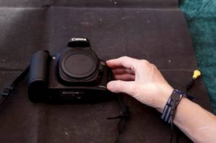
Turn the
camera off and remove the battery.
|
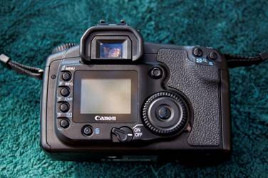
Removing The Back Cover |
|
|
|
|
|
|
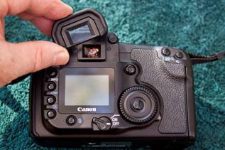
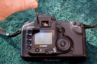
1. Remove the eyepiece. Place it aside
somewhere safe. |
|
|
2. Remove three screws Two each side of the
eyepiece and one to the left of the menu button. |
|
|
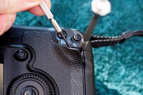
3. Remove screw behind rubber grip Carefully lift the
corner of the rubber grip to expose the fourth screw which is now removed. |
|
|
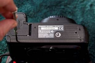
4. Remove the two
screws on the bottom of the camera. Only remove the two
screws at the back of the camera in the back case. Be careful that the
back of the case does not come off at this stage. |
|
|
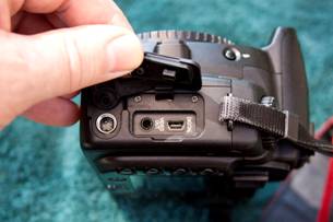
5. Remove the two
screws next to the digital and video connectors. |
|
|
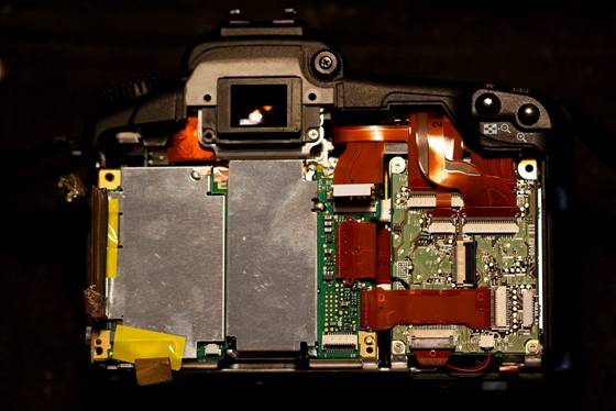
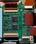
6. Open the back
compartment. Carefully open it to
the right as shown. Be careful not to strain the ribbon connector which
connects it to the main circuit board. You will need to
unlock the ribbon connector on the circuit board by carefully slipping a
small flat blade screw driver between the flat cable and the connector lock
gently prying it up to unlock the connector. Once unlocked, carefully pull
the ribbon cable out of the connector and put the back cover safely aside. |
|
Removing
The LCD |
|
|
|
|
|
|
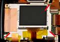
7. With soldering iron and solder sucker remove excessive
solder from LCD frame in top right hand corner. |
|
|
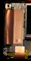
8. Peel back all three copper noise reduction sheets. The
third one with the screw hole in it is underneath the large sheet. These are sticky on
the back, so be careful not to tear the thin sheets of copper. |
|
|
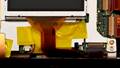
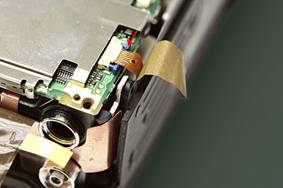
9. Remove the yellow tape and carefully removed the two
wire connector with the Red and Black wires. Use some small pointy nose
pliers and pull the connector out being careful not to pull on the wires. 10. Release the ribbon connector holding the ribbon cable
for the LCD and pull the ribbon cable out of the connector. |
|
|
11. Remove the three screws holding the LCD bracket and
now remove the LCD putting it aside. |

|
Removing
The CMOS Sensor Shield |
|
|
|
|
|
|
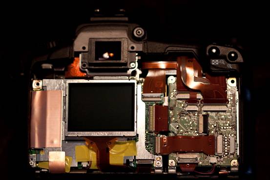
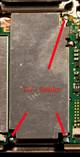
12. Using a small soldering iron and a solder sucker,
remove the solder from the three lugs connecting the CMOS Sensor shield to
the PC. Once its free, remove the CMOS Sensor shield and put it safely aside. |
|
Removal Of Large PCB On LHS |
|
|
|
|
|
|
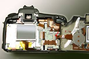
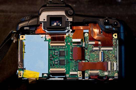
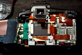
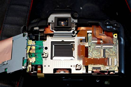
13. Unlock the three ribbon
connects on the main board on the LHS of the camera and remove the three
ribbon cables. You can carefully use a small screwdriver or a toothpick thru
the holes of the cables to slide them out of the connectors. 14. Unlock and slide out the two ribbon cables that go to
the CMOS Sensor. (Top and bottom LHS of this picture insert). |
|
|
15. Remove yellow tape on LHS bottom corner to reveal
another ribbon cable and connector. 16. Unlock and remove ribbon cable. Note:This ribbon cable connector unlocks using a different method to
all the rest. Put a small flat blade screw driver behind the blue lugs at
each end of the connector and pull both of them out towards the back of the
camera. Then gently slide the ribbon cable out. |
|
|
17. Now lift and over the PCB to the left, being careful
not to stain the blue and white wires still soldered between the PCBs. |
|
Removing the CMOS Sensor Assembly |
|
|
|
|
|
|
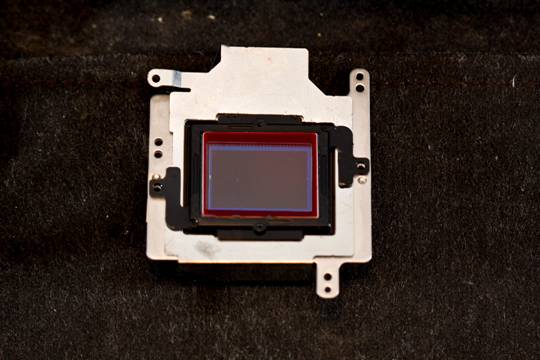
18. Remove the four screws holding the CMOS Sensor
assembly to the main chassis. 19. Remove the CMOS Sensor assembly. |
|
|
|
|
|
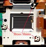
Caution: If you need to tip the camera over to recover a
dropped screw for example, the six brass shims shown will dislocate. There
are three locations for these shims, so there are two shims at each location. |


|
Removal of Hot Mirror IR Blocking Filter |
|
|
|
|
|
|
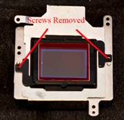
20. Remove screws from IR assembly. Up until now
everything is reversible. From here on however it is very unlikely
that you can reverse the changes. If you have some
thin cotton gloves, it would be a good idea to wear them as you don’t want to
touch the CMOS Sensor by mistake and leave grease on it. |
|
|
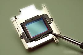
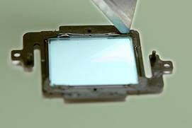
21. Remove the IR blocking filter assembly. This is glued in so
you will need to work your way around the assembly leverage it with a small
flat bladed screw driver. Once you have filter
assembly containing the filter, put the sensor assembly aside protecting it
from any dust contamination. |
|
|
22 Cut and remove the glue holding the IR filter in the
black plastic mould. Once the filter is
removed, I cleaned the black plastic frame to remove the remains of the glue. |
Cleaning The
CMOS Sensor
With the
camera now re-assembled and fully functional it should comes as no surprise
that you need to clean the CMOS Sensor.
First check
the CMOS Sensor for dust by taking a test image. To do this fit a normal
terrestrial lens to the camera and go outside. Take a shot of some clear blue
sky, or white smooth clouds. When exposing the test image ensure your lens is
stopped down as far as it can go, f22-32 for example.
The shutter is set to give the correct exposure. Dont
forget when you focus on the focusing screen, the image will not be sharply
focused on the CMOS Sensor.
Now
download the image and view it @ 100 percent (actual pixels ).
This will show if you have dust on the CMOS Sensor and where its
located.
I use a set
of Sensor Brushes to clean the mirror chamber and the CMOS Sensor surface. You
need to be extra careful now as there is no longer the IR blocking filter
protecting the surface of the CMOS Sensor. You will more than likely need to
take more test images, check for dust and clean a few times until you are happy
the CMOS Sensor is dust free.
Fitting The
L / UV & IR Filter
The final
step now is to fit a suitable L filter to suit your set-up. With the extra Red
Spectral Response you may get purple/violet fringing around bright stars on
long exposures without the addition of a suitable filter.
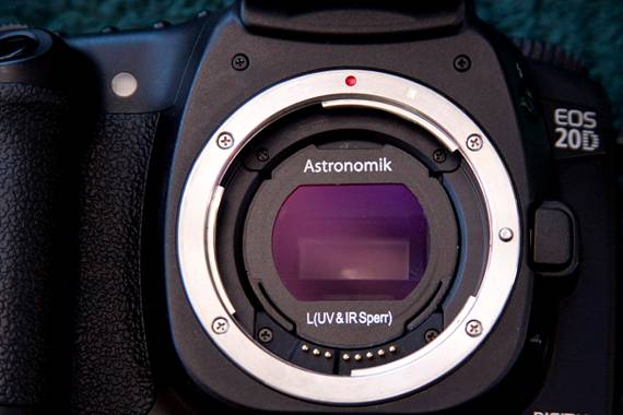
The filter
can be fitted externally anywhere past your T-Ring adaptor or by using a EOS Clip Filter as shown in the image below. The added
advantage of Clip Filter being it helps keep dust out of the mirror chamber
when you are doing this in the dark during an imaging session.
|
|
|
|
|
|
|
|
|
|
Astronomik EOS Clip-
Filter |
|
|
Written
by: Chris
James |
|
|